People are often unsure of what a brushless generator is, how it works, and what its benefits are. Brushless generators are becoming more and more popular as people learn about their advantages over brushed generators.
They require less maintenance, last longer, and produce less noise. They can be found in various settings, from construction sites to residential neighborhoods.
Read on to learn more about brushless generators, why they require less maintenance, brushed vs. brushless generators, and what other factors you should consider when choosing a generator.
What is Meant by Brushless Alternator?
As you may already be aware, an alternator is a synchronous generator that converts mechanical energy produced by an engine (by burning a fuel source like gasoline or natural gas) to electrical energy during a power outage.
The field winding is the portion of the alternator made from a laminated steel core and coils of conductors that receives voltage from a power source and produces magnetic flux. While the armature is also made up of laminated core and conductor coils, it is where the output power gets generated by the process of electromagnetic induction. Either rotor or stator can be the field or armature of the generator, based on its design and construction.
In the early days of power generation, the utilities generated and distributed both DC and AC currents. This current was generated in the rotor and captured via carbon brushes and communicator (DC) / slip rings (AC). Such machines are known as rotating armature machines.
With the advances in power generation, standard utility power changed to AC only. In addition, utilities started using rotating field machines where a rotor acts as the field winding and a stator as the armature.
In this new arrangement also, slip rings and brushes still found a place. They carried the excitation current to the field winding on the rotor. The machines where the brush arrangement is used in either the rotor or the armature are known as brushed alternators. However, the arrangement still suffered from reliability, maintenance costs, and versatility issues, as you will see later.
Efforts were focused on eliminating the brush arrangement and led to the advent of a brushless generator. Brushless generators carry a separate exciter and use magnetic induction between the exciter stator and the exciter rotor winding and a rectifier assembly to supply DC current to the main rotor winding. These machines work without the sliding ring and brush arrangement, thereby known as brushless alternators.
You will understand the functioning of a typical brushless alternator in the following section.
How Does A Brushless Generator Produce Power?
For easy understanding, you can consider brushless alternators to be a combination of two alternators built on the same shaft end to end. Together, both alternators combined in a small brushless ac generator may present an appearance of a single unit, but you can easily distinguish them as two separate items in larger machines.
The excitation for such systems is provided by an auxiliary synchronous generator called an exciter mounted towards the one end of the main alternators’ shaft.
The excitation system for any modern alternator would normally have the following features:
- The exciter has stationary field coils on the stator and the armature on the rotor.
- The AC voltage generated by the exciter armature is rectified by rotor-mounted diodes and fed to the main rotor field windings.
- Solid-state analog-type automatic voltage regulators are provided for voltage regulation.
- The AVRs are fed from the alternator’s output power or an independent power source for their functioning. This independent source can be an auxiliary stator winding or a Permanent Magnet Generator (PMG).
The diagram for the excitation system is shown below. The system’s main parts are the main rotor, exciter field, exciter armature, rotating rectifier unit, AVR, and independent permanent magnet generator power supply. Some texts also call the PMG synchronous generator the sub-exciter.
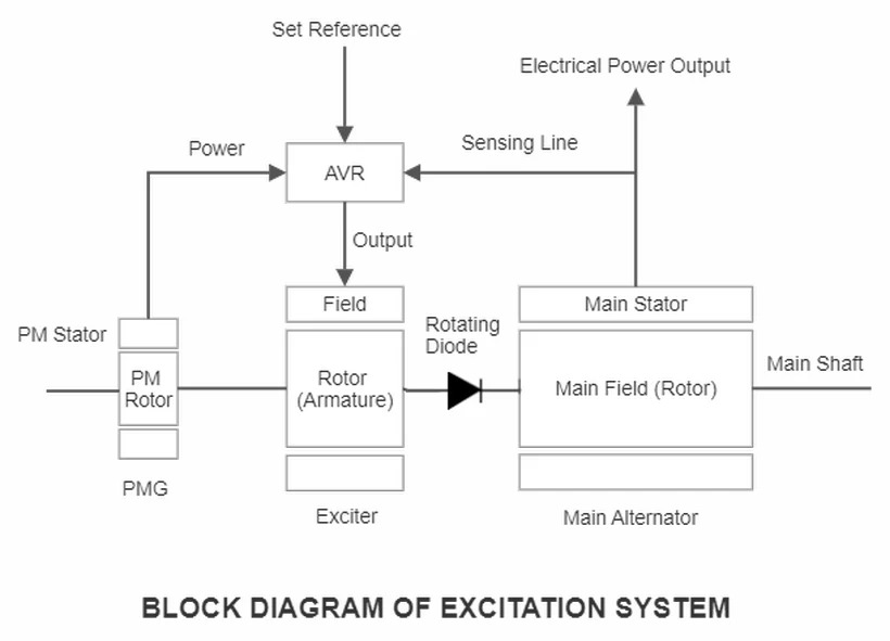
The Excitation System
The main rotor winding requires high levels of power. This is provided by the exciter armature and the rotating rectifier assembly. The required level of excitation current and, thereby, the correct magnetizing ampere-turns in the main rotor are achieved by controlling the voltage generated in the exciter armature.
AVR carries out this job by dynamically regulating the current value in the exciter field winding. The current value to the field winding is decided by an internal closed-loop control system that continuously senses the main stator output volts and compares it with the “Set voltage.“
The system tries to bring the output voltage of the alternator to within 3% of the set value within 0.25 to 0.3 seconds.
Main Rotors
The main rotor has a laminated salient pole construction with directionally wound coils. The adjacent poles carry opposite polarities. The magnetic field strength depends on the current flowing through the field winding unless the magnetic flux path saturation sets in. The flux density depends on the properties of electrical steel, the number of poles, the rotor speed, and the saturation levels of various paths in the magnetic circuit.
Once the rotational speed of the rotor is maintained to produce the required output frequency, the alternator’s stator voltage is a function of the rotor’s magnetic flux strength.
The field winding resistance is in the range of 2 to 3 ohms. The current in the field coils will obviously depend on the rating of the alternator and how much power in kVA or kW the machine is delivering. The field electrical current may vary from 10 A in smaller alternators to 150 A in large ones at the rated connected load. During starting of the motor loads, this value may rise to about 250 A. Most rotors are constructed to perform under short-term over-speeds of about 20 to 25%.
Automatic Voltage Regulators
Certain literature also calls them Voltage Control Units. In a brushless generator, the AVR has one electrical output, two inputs, and an internal voltage reference signal.
- Output signal – The AVR output goes to the exciter field winding.
- Set Reference – This signal is generated within the AVR internal circuitry and acts as a steady-state set value reference for the alternator’s output voltage.
- Input signal 1: The actual sensed value of alternator Volts.
- Input signal 2: The power supply to the AVR.
AVR Operation
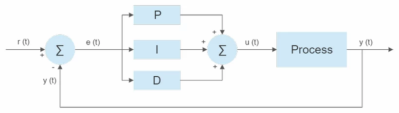
An Automatic Voltage Regulator carries a PID closed-loop control system (as shown above) to perform its basic function. PID stands for Proportional – Integral – Derivative control system. In any control system, the difference between the controlled and reference value parameters is termed an “error E.” The controller then generates the control signal “C” to bring the error down to zero. In a PID controller, the control signal constitutes the following components.
- Proportional element Cp – It produces a control output that is directly proportional to the error E. This means the larger the error, the larger the value of the proportional control signal Cp.
- Integral element Ci – The integral component in a PID controller generates a control output that is proportional to the sum of the instantaneous value of the errors over the time duration that the error has persisted. You may note that the integral term depends both on the magnitude of the error and its duration. A small error persisting for a long time will result in a larger control signal, as will a large error existing for a small time. The basic function of integral control is accelerating the process’s movement towards the set point and completely eliminating the steady-state error. The associated drawback with the concept is the likelihood of overshooting the set value as the control signal depends on accumulated errors till the current state.
- Derivative element Cd – This element produces a control signal dependent on the rate of change of error. The derivative action effectively predicts the system’s upcoming behavior and improves the system’s stability and settling time.
In recent times digital AVRs are becoming popular, albeit at increased costs.
Power for the AVRs
The two methods of powering the AVRs include using a self-excited alternator and the separately excited alternator configuration.
Self Excited Alternators
These are used in cost-effective brushless generators where the electrical energy for the functioning of AVR is derived from the sensing input. Such generators are also referred to as shunt excited. The alternator performance is severely limited under overload conditions as the resultant voltage dip limits the power availability to the AVR.
Separately Excited Alternators
In this arrangement, the AVR’s electricity is obtained from an independent power source, removing its reliance on the alternator.
One such method is to embed an auxiliary winding in the stator to feed the alternating current to the AVR. However, in this arrangement also, the voltage of the power received by the AVR will vary depending on the excitation level in the main rotor’s field winding to cater to the different load conditions.
The best option is to go in for a totally independent and isolated powering of the AVR by having a pilot exciter (also known as a sub-exciter) in the form of a permanent magnet generator.
Exciter
An exciter is an electrical assembly located within the alternator frame. It is basically an alternator with its stator acting as the field winding, and its rotor (located next to the main rotor) works as the armature. The two rotors are electrically separated by the rotating diode assembly.
AVR acts as a DC power source for the exciter and provides a suitable control signal from its PID controller. The armature for the exciter is built with a laminated steel core housing a 3-phase winding in radial slots close to its periphery. This winding provides a suitable output voltage and current based on the needs of the main field winding.
The exciter basically acts as a mechanical power amplifier that converts the 200 to 400 W electric energy from the AVR to several kW power demanded by the main alternator’s field winding. This additional energy is provided by the generator’s engine running on diesel, gasoline, or other fuels.
Rotating Diode Assembly
The diodes in the rotating diode assembly are connected in a 3 phase full wave bridge rectifier configuration. They are selected to
- Have safe operating margins in their current carrying and voltage withstanding capabilities in relation to the exciter armature and main field windings.
- Withstand harsh operating conditions encountered due to step changes in load or rough synchronization while paralleling two generators.
- Withstand the centrifugal forces due to the continuous rotation of the assembly.
Many alternators carry an Independent Diode failure Detection Module (DFD) to monitor the diode assembly or its failure. The DFD module is located between the AVR and the diode assembly. It looks out for any unusual ripple current in the feed to the exciter field winding. The presence of ripples indicates an open circuit fault in the diode.
There can be a short circuit in the diode from a high Peak Inverse Voltage (PIV) that may get applied to it, causing the breakdown of the PN junction. This makes the diode non-rectifying resulting in an overload on exciter armature and main field winding. AVR compensates by increasing current to the exciter field and eventually shuts down due to over-excitation protection.
The rotating diode assembly has surge-suppressing voltage-dependent resistors (VDRs) carefully chosen to protect the diodes from the damaging levels of PIV.
You can also see a brushless generator in action to learn more about how the excitation process works.
What Are the Main Advantages of Brushless Generators?
With fewer moving parts and a lower noise level, there are several reasons to choose a brushless generator instead of a brushed model. Read on to learn more about them.
Maintenance
One of the main downsides of a brushed generator is that the moving parts, like sliding rings and the carbon brushes placed on the brush holder (to remain in firm contact with rings), require more maintenance. When the main rotor spins, it puts a lot of wear and tear on the brushes.
Most brushed generators use carbon or graphite brushes because these materials have excellent conductive properties. However, carbon and graphite aren’t very durable materials.
Over time, the brushes will break down, collect dust, and become less effective at transmitting electrical current. You’ll have to open the generator and replace or repair the brushes.
Replacing the brushes can become expensive. Plus, taking the generator apart is time-consuming, and everyone may not have the skills to carry out the replacement.
Even though brushless generators tend to have a higher price tag, you’ll save time and money on maintenance since there are no brushes to replace. Overall, brushless models tend to have a longer lifespan.
Noise Level
Another advantage of brushless generators is the reduced noise level. Having carbon brushes maintain contact between the rotor and its housing can get loud due to friction.
Since you only have two rotors that spin and create a magnetic field, there is much less noise produced when you operate a brushless generator.
Noise level can seem like a detail, but it’s an important consideration for generators that will run for a long time.
Do Brushless Generators Have Any Downsides?
There are a few potential downsides to consider if you’re thinking about getting a brushless generator.
Cost
Brushless alternators have a higher price tag than their brushed counterparts. Depending on what you need a generator for and how often you will use this device, you might not be able to justify the higher initial cost.
However, the cost of using your generator will even out over the years since brushless models require less maintenance and can even use less gas, especially when operating on a low setting.
It’s important to consider how often you will use your generator and how long it will typically run. If you plan on using your generator regularly and for several hours at once, the higher initial price of a brushless model makes sense.
Size and Weight
Brushed generators have a single rotor. Brushless models use a primary and exciter rotor. The additional rotor can add to the bulk and weight of the generator.
It’s not a major downside since an exciter rotor isn’t a particularly large part, but the size and weight of a generator can be important for portable applications.
Repairs
We’ve already established that you will need less frequent maintenance and repairs with a brushless generator since there is no need to replace failing brushes.
However, because these generators use two rotors, you might be looking at an expensive repair bill if the exciter rotor fails. The overall maintenance cost is much lower with a brushless model, but you should know that an additional part can potentially fail and be expensive to replace with the exciter rotor.
Using an exciter rotor can also make troubleshooting issues more complex since these devices have two main parts that can fail. If your generator stops working, you might not be able to pinpoint the root cause of the problem without an expert looking at the device.
This guide for faulty brushless generator repair should give you a better idea of what actions you might need to perform to get your generator running properly.
Conclusion
Did you learn something new about brushless generators with our list of tips and facts? If you’re in the market for a new generator, we recommend considering a brushless model to save on maintenance and get a generator with a longer lifespan.
Thank you for the paper very precise and complete. I want to add that my experience with brushless generators in aviation shows the machines have a much lower heat rejection than the brush type ones. The friction of the brushes with the commutator is a challenge to be cope with in the air cooled machines.
My brushless generator only has one rotor with two windings. I have taken it apart and can see both windings on opposite sides of the rotor. Each winding has a diode along with a resistor connected in series with the windings. If I understand correctly, this is what creates the voltage in the main stator windings output. I cannot see the exciter windings on the rotor. I think my exciter windings are on the stator. I say this because there is a set of wires that are connected to a capacitor coming from the slots of the stator. I have tried to reflash this exciter winding using a 12VDC battery but the F1 and F2 are not indicated on the wires. I don’t know if doing this both ways will matter. If you have any other suggestions I’d appreciate your help. Yes, the generator was working a couple of years ago but sat and now seems to have lost its residual magnetism. I don’t know how to restore it.
Can you indicate the make and model number of your generator