Many people don’t understand what Total Harmonic Distortion is or why it’s important, and they may not be aware of the other adverse effects of harmonic distortion.
The THD value is a critical factor in assessing the power quality of any generator model and the loads they are powering. Harmonics beyond acceptable limits can cause several problems, including equipment overheating, vibrations, noise, damage or malfunctioning of electronic equipment, interference with communication and control circuits, reduced system efficiency, and even fires.
The article below will give you critical insights and valuable information about harmonics, their generation, how they affect the systems, their acceptable limits, Generator THD, and much more.
You can go through our separate article on “Mathematical Treatment of Harmonics in Electrical Systems” to know all about the basics of harmonics, and their mathematical treatment.
Why & How are Harmonics Produced?
The distortion is introduced in the power system at the source and the load side.
Source-related issues
A pure original sine wave is a theoretical concept and can be produced only by an ideal AC generator built with
- A perfectly distributed stator winding
- A field that creates an absolutely uniform magnetic field.
In practice, both these conditions cannot be achieved, and the output waveform from any working AC generator deviates from the perfect waveform.
Rotor pole Tip
In AVR generators, the shape of the waveform depends on the physical shape of the rotor pole head. A rotor with a square-shaped pole head will generate a square flux wave. This will induce a lot of harmonic frequencies in the stator winding.
Many manufacturers bevel the pole tips, leading to an increase in the air gap and hence a reduction in flux at these positions, resulting in a better waveform than the square wave.
The best flux waveform is achieved by rounding the pole face at a radius. The center of the rounding is different than the stator core. You can say that the waveform deviation factor largely depends on how much effort goes into shaping the pole heads, leading to increased costs.
Load-related issues
The use of non-linear loads in modern times is ever-increasing. Non-linear loads are the biggest source of harmonics in any network. The most common types of non-linear loads include:
- Static converters with rectifier bridges that are made up of diodes and thyristors.
- Other power converters such as cyclo converters and dimmers.
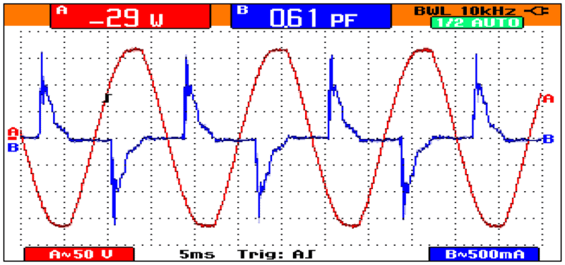
- Lighting systems comprising of fluorescent lamps and discharge lamps. In such systems, the largest single harmonic is the third order, with a ratio exceeding 100% percent in certain cases. Waveform for Compact fluorescent lamp shown below.
- Arc furnaces
- Saturated reactors
Usually, we keep focusing on the source side, but the harmonic currents generated by non-linear loads greatly impact the total harmonic distortion in the power systems. Let us understand how?
Voltage Waveform Distortion
Harmonic currents flowing through any impedance in an electrical power distribution system will create harmonics of the same order. A 5th-order harmonic current will produce a 5th-order harmonic voltage. You may refer to the below diagram to understand the concept.
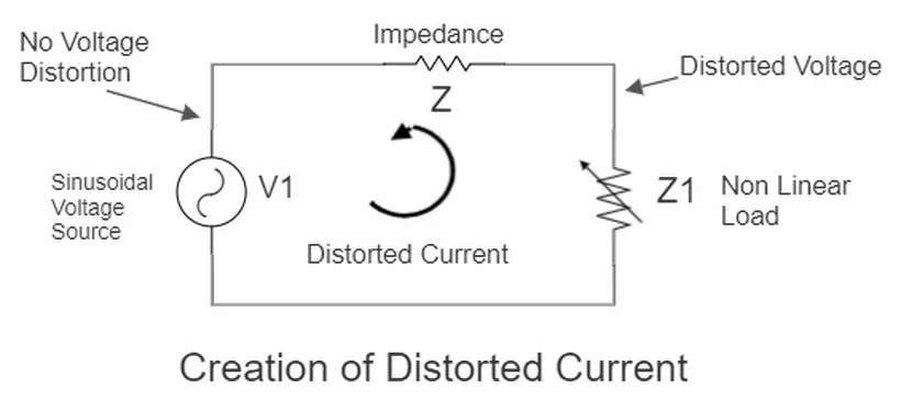
 is a sinusoidal voltage source that produces a clean sine wave of the fundamental voltage. This source is connected to a non-linear load
  through a circuit with impedance Z. The load will produce currents of multiple harmonic frequencies. Each of these currents will produce a voltage drop against the impedance Z.
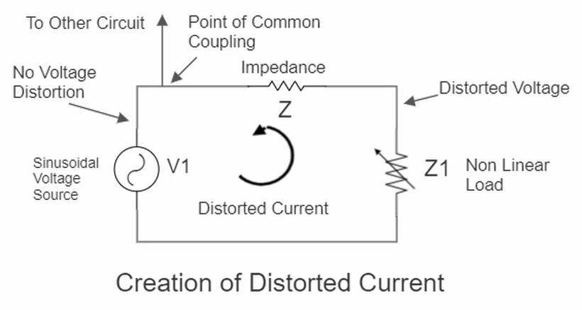
Hence, the voltage waveform at the source terminals, which was undistorted earlier, becomes distorted now. Anything connected at the source terminals in parallel with this non-linear load will start experiencing voltage and current harmonics even if that load is linear. This point where both the loads are getting connected is often referred to as the Point of common coupling.
As the load impedance is higher than the network impedance Z, which in turn is higher than the source impedance  , the voltage distortion is maximum near the load and least near the source. To say the same reversely, even if the voltage distortion levels are low at the source, they can reach unacceptable levels at the load.
As seen by you above, the harmonic currents interact with the system impedance to cause the voltage drops. Hence the magnitude of voltage waveform distortion directly depends on the magnitude of the source impedance. The lower the source impedance, the less distortion is there.
Is Generator THD Important?
The source impedance of any portable generator varies with time after a load change till the system is stable again. The generator with the lowest internal reactance to the change in the instantaneous current value for any given load will produce the lowest total harmonic distortion, THD.
You can understand this with the following logic. When you suddenly switch a relatively large load on a small generator, the voltage and frequency values fluctuate till the AVR and the frequency governor adjust to this load change. Hence, based on the design and size of the generator, it may have a much greater internal reactance to a sudden change in load. This is often referred to as the sub-transient reactance.
This is why the non-linear loads work fine on utility power and produce much higher total harmonic distortion on generators. Hence, the generators with comparatively large sub-transient reactance and high THD levels in the inherent power waveforms will magnify even the small amount of harmonics fed back by the load to produce a much higher total harmonic distortion in the voltage.
The matters are even worse if a large share of the generator’s capacity is taken up by non-linear loads.
Other Adverse Effects of Harmonics
Different types of loads experience the different detrimental effects of the harmonics. These effects are classified into instantaneous effects and long-term effects. The long-term effects are due to heating. You can learn the details about these effects in the upcoming sections.
Instantaneous Effects
The harmonic voltages can adversely impact the electronic equipment, cause vibrations & noise, and cause interference with communication and control circuits.
Impact on electronic equipment
The harmonic voltages can
- Alter the switching conditions of the thyristors by shifting the zero crossing of the voltage wave, thereby causing the controllers to malfunction.
- Cause errors in induction disc type of energy meters.
- Ripple control receivers – the relays used by the utilities for central control can be disturbed if the harmonic frequency matches the control frequency of these relays.
Vibrations and Noise
- The harmonic currents can produce large electrodynamic forces to cause vibrations and acoustical noise in transformers and reactors.
- Harmonics can produce their own rotating fields in the rotating machines, resulting in pulsating mechanical torque and vibrations.
Interference with communication and control circuits
- Harmonic currents in power distribution circuits cause disturbances in communication and control circuit lines running parallel to them. The impact depends on the parallel length, separation in two lines, and harmonic frequencies,
Long-term effects
The long-term effects are caused by mechanical fatigue due to vibrations and heating. They include
- Capacitor heating occurs due to losses caused by conduction and dielectric hysteresis, which in turn are proportional to the square of RMS current. High THD can cause heating and dielectric breakdown.
- Heating in rotating machines: Harmonic distortion causes additional copper and iron losses in the stator and in the rotor. The losses are due to differences in the speed of the rotor and the harmonics-inducing rotating fields.
- Heating in Transformers: There are additional losses in transformers caused by (1) hysteresis and eddy current in the magnetic circuit due to harmonic frequencies and (2) by the skin effect due to increasing the copper resistance with frequency. These losses result in additional heating of the transformer.
- Heating of cables: Cables carrying harmonic currents get overheated due to (1) an increase in RMS current, (2) an increase in the core resistance due to pronounced skin effect at higher frequencies, (3) an increase in dielectric losses in the insulation of the cable with an increase in frequency, and (4) proximity effect.
Generally speaking, any electrical equipment (1) subjected to voltage harmonics or (2) passing the current harmonics will have increased energy losses leading to a temperature rise.
Adverse effects On portable generators
Let us quickly make you aware of the impact of excessive total harmonic distortion, THD, on the performance of portable generators.
Erratic AVR functioning
An Automatic Voltage Regulator (AVR) will sense the incorrect voltage at the stator terminals if the amount of THD-V is high and regulate the generator to the wrong levels.
The AVRs on the larger generator sets are designed for non-linear loads and use filters on the voltage sensors. They sense all the phases and carry out the true RMS calculation. The prohibitive costs of such a system do not allow the use of these sophisticated AVRs on portable generators.
Erratic speed fluctuations
AC frequency governor can easily malfunction due to high total harmonic distortion. These governors obtain speed feedback signals by sensing the frequency of output voltage inside the AVR unit. These frequency measurements involve sensing zero crossing of the voltage waveforms.
High total harmonic distortion can cause problems in this scenario involving multiple zero crossings in one cycle leading to incorrect measurements and instability of the speed governing system.
Limits the Continuous Load Ratings
The harmonics cause overheating of the stator and rotor windings. This, coupled with the instability due to erratic self-excitation at higher leading power factor loads, affects the generator’s continuous load ratings.
Acceptable limits & recommendations
You may wonder, “How much THD is too much?” or “What is normal THD?“. We will present answers to all of your similar questions in this section.
The general permissible limits for Total Harmonic Distortion for different types of equipment are:
- Cables: Core shielding voltage distortion = 10%
- Sensitive Electronics: Voltage distortion = 5%, however, the individual harmonic percentage should be limited to 3%.
- Synchronous machines: Stator current distortion = 1.3 to 1.4%.
- Asynchronous machines: Stator current distortion = 1.5 to 3.5%
- Capacitors: Current distortion = 83% with an overload of 30%. Overvoltages can be up to 10%.
Limits as per the Standards
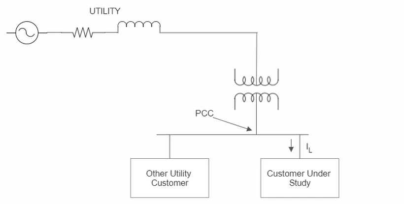
IEEE Std 519 has the recommended practices to guide you. The general opinion is that they are not very hard to comply with. The standard lays down the goals for designing electrical systems with linear and non-linear loads. The limits in the standard and the recommendations are not binding. All the limits are defined at the point of the common coupling (PCC) shown in the diagram below.
If the customer under consideration has his own transformer, the PCC is on the MV side.
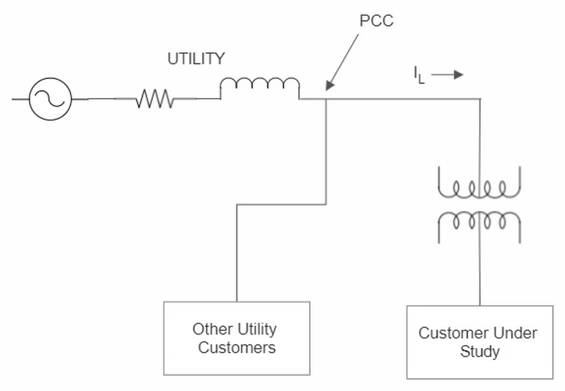
If the customer under study is fed from the same LV transformer as other customers, the PCC is on the LV side.
A very frequently asked question is, “if all your loads are complying with IEEE 519, would your system comply with it”. The answer is that it is very difficult to ensure all your equipment, like LEDs, will use harmonic control. You can ensure load-side compliance for bigger equipment like VFDs, rectifiers, etc.
The standard makes the assumption that by limiting the non-linear current injections to the network by the users, you can keep the voltage distortion below acceptable limits. The limits indicated below apply only at the point of common coupling and not on any individual piece of equipment.
Voltage Limits
The table for voltage limits is shown below. It is organized based on the voltage limits – LV, MV, and HV. It gives the line to neutral voltage limits at the PCC for individual harmonics and the total harmonic distortion percentage. The THD percentage has increased from 5% to 8% in 2014, as the loads are not affected at low THD levels of voltage.
| Bus Voltage V at PCC | Individual harmonic % | Total Harmonic Distortion |
| V ≤ 1.0 kV | 5.0 | 8.0 |
| 1 kV < V ≤ 69 kV | 3.0 | 5.0 |
| 69 kV < V ≤ 161 kV | 1.5 | 2.5 |
| 161 kV < V | 1.0 | 1.5 |
IEE 519 – 2014 – Voltage Distortion Limits
Current Limits
The table below shows the current limits as the percentage of load current. The table is organized based on the short-circuit current and load current ratio at the PCC, denoted as Isc / IL. It gives the recommended maximum value of percentage for each harmonic order. It also gives the limit for total demand distortion TDD.
| Maximum Harmonic current Distortion As Percentage of IL | ||||||
| Individual Harmonic Order (Odd Harmonics) | ||||||
| ISC/IL (R) | 3 ≤ h <11 | 11 ≤ h <17 | 17 ≤ h <23 | 23 ≤ h <35 | 35 ≤ h <50 | TDD |
| R<20 | 4.0 | 2.0 | 1.5 | 0.6 | 0.3 | 5.0 |
| 20≤R<50 | 7.0 | 3.5 | 2.5 | 1.0 | 0.5 | 8.0 |
| 50≤R<100 | 10.0 | 4.5 | 4.0 | 1.5 | 0.7 | 12.0 |
| 100≤R<1000 | 12.0 | 5.5 | 5.0 | 2.0 | 1.0 | 15.0 |
| R≥1000 | 15.0 | 7.0 | 6.0 | 2.5 | 1.4 | 20.0 |
The important points to note from the table are:
- If the ratio Isc/IL is small, the limit on TDD is more stringent, as in this case, the current distortion will eventually cause voltage distortion at the PCC.
- A high value of current THD will cause heating in your equipment.
- The even harmonics value should be limited to 25% of the odd harmonics limits.
- DC offset or harmonic of order zero is not allowed.
- The limits for the power generation equipment are the same as that for the ISC/IL ratio of 20.
Conclusion
After reading this article, we hope you understand harmonics better. If you still have any questions or want to know more about generator total harmonic distortion, please post your comments below, and we will do our best to answer them. Stay safe and keep generating!