Portable generators are becoming increasingly popular, but many people don’t really understand how they work.
A portable generator can be a lifesaver during a power outage, but it can also be used for camping, tailgating, or any other outdoor activity. However, there is a lot of confusion about how they work and what the different parts do.
This article will explain how do portable generators work and what each system or part does. We’ll also talk about some of the benefits of using an automatic voltage regulator (AVR), its types, and various safety and control features.
The Simple Basics
In simple terms, a generator is a machine that converts mechanical energy (derived from chemical energy by burning fuels like gasoline, natural gas, diesel, propane, or from the elements like wind, water, etc.) into electrical energy. Generators come in various types and electrical power ratings to serve different applications.
Types of Generators
Generators are classified into many different types in many different ways based on
- Construction (brushed, brushless, inverter),
- Quality and the duty they serve (residential, commercial, construction),
- The application (portable, standby generator), and
- The type of fuel used (fossil fuels like natural gas, propane, gasoline, diesel, or renewable fuels like hydrogen or solar energy).
While selecting the fuel for your generator, you must consider various factors like the cost and life of the engine, storage requirements, fuel consumption, fuel stabilizer requirements, size of the gas tank, etc.
Ratings
The electrical power output of any portable generator is measured in a unit called watts. The continuous watts the generator produces while running at its rated load are known as running watts.
While starting reactive loads like large motor-driven appliances, it has to supply extra power, known as the surge power, while the total power requirements of these loads while starting is known as the starting watts.
Other ratings include voltage, frequency, total harmonic distortion, noise levels, etc.
Alternator Ratings
Alternator ratings depend on the voltage they are designed to produce and the maximum current they can supply to the load continuously.
This maximum rated current of an alternator further depends on the permissible temperature rise in the conductor, a function of the insulation used. Temperatures existing beyond this value for a long time will cause deterioration in the insulation and eventual failure. Hence, high temperatures are prevented by the circuit breakers that consider current beyond the maximum limit as an overload on the generator.
For example, if the design ambient temperature is, 20 Deg C and the permissible max temperature that insulation can safely withstand continuously is 90 Dec C. The current that causes a 70 Deg C rise in the stator conductors’ temperature is the alternator’s maximum rated current.
Electricity & Magnetism
Irrespective of the type or rating of the generator, all electrical generators eventually depend upon Faraday’s law of electromagnetic induction to convert mechanical energy to electrical energy.
As per the law, an electromotive force (emf) is induced in a coil if either (1) the coil moves (cuts) through the magnetic field or (2) the magnetic flux moves (cuts) through the coil. This means that a relative motion between the coil and magnetic field is necessary to produce the voltage (emf).
Working of An Elementary Generator
The part of the generator that produces the magnetic field is known as the field, and the part in which the voltage is induced is known as the armature. Also, the relative motion can only be established if the generator carries two mechanical parts, one rotating, and the other stationery. The rotating part is always called the rotor, and the stationary part is the stator.
The rotor always functions as the armature in any DC generator, where the emf gets induced. However, in AC generators, either the stator or rotor can take over the role of the armature. Accordingly, AC generators are classified into rotating armature or rotating field types.
In rotating field machines, stationary armature windings can be directly connected to the loads and do not require slip rings and brushes for the purpose. The voltage applied to create the rotating field is mostly a low DC voltage eliminating any slip ring arch-over possibility.
On the other hand, rotating armatures are generally very difficult to insulate and can cause arching or short circuits at higher voltages.
For this reason, all portable generators that you use to produce electricity at your home, site, or RV are of the rotating field type. The stator is made from a laminated iron core that carries the embedded windings in them.
Working of Practical Generators / Alternators.
You were introduced to the differences between a generator and an alternator in our article on the topic. While certain basic concepts were introduced in that article, you will fully understand the complete functioning of an alternator by the end of this article.
Most rotating field AC generators carry an alternator and a very small DC generator constructed in the same unit. The stator supplies the AC electrical power to the load through the AC power output terminals. The DC generator, known as the DC exciter, feeds DC power to the field winding to create the magnetic flux.
The exciter is a self-excited, shunt-wound DC generator. The shunt-connected field winding in the exciter creates an intense magnetic flux area between its poles. When the exciter armature rotates in this field, a voltage is induced in its windings.
This voltage output from the armature gets converted to DC voltage in the commutator of the exciter and fed to the main alternator’s field winding through the slip rings and brush arrangement. The fixed polarity alternator field produced by the DC current from the exciter rotates due to the movement of the rotor, thereby linking and inducing an emf in the stator windings.
There are two types of rotors commonly used in any rotating field alternator.
- Salient pole rotors
- Cylindrical rotors
Cylindrical rotors are used in high-speed alternators driven by a turbine. Salient pole rotors are bigger in size, have more weight, and are ideal for slower spinning rotors on any typical portable generator.
Parts of a Portable Generator
In this section, you can familiarize yourself with the main parts of portable generators and how do portable generators work. These major parts include the Internal combustion engine, alternator, automatic voltage regulators, frame, fuel system including tanks, starting system, control panel, engine management controls, power outlets, safety mechanisms, cooling system, and bearings.
We had already discussed at length the main features expected in any modern-day portable generator in our article titled “What To Look For In A Generator.” We shall not be repeating those details. This article is intended to appraise the technical aspects and functions of the major parts.
Internal Combustion Engines or Prime Movers
Small engines (2 to 25 HP) used in the portable generators are relatively simpler in design than their big brothers, boasting about 100 HP or more. Unlike cars and other engines, they run at a fairly constant speed or change speed slightly in response to changes in loads and do not have to accelerate or deaccelerate frequently. Also, they are not connected to radiators or many microchips controlling or monitoring them.
These engines are mostly of 4-stroke or 4-cycle variety. Every small engine carries five main systems, as listed below.
- Fuel supply system.
- Compression system.
- Ignition system.
- Lubrication and Cooling system.
- Governor or Speed Control system.
There are two other systems, namely the starter system, including the generator battery, starter motor, and battery charging system, and braking system. The first five systems are the core systems required to generate power, and the last two are for safety and convenience.
Each of these systems is a vast topic in itself, so we will only highlight their salient functions.
How Does an Internal Combustion Engine Work in a Portable Generator?
The Starter System:
The engine starts when you pull the rewind cord or press the start button to bring the starter motor into play using the battery power.
The Fuel System:
It usually comprises the generator fuel tank, fuel filter, fuel line, fuel valve, fuel switch, fuel pump (some models if the tank is mounted low), and carburetor. The fuel line connects the tank and the carburetor. The carburetor is a mixing chamber having a throttle and a choke.
A metering device called a jet allows fuel from the carburetor fuel bowl into the emulsion tube located in the pedestal. The fuel and air first mix here before reaching the main passageway in the carburetor called the throat, where further mixing happens.
A word of caution – never leave fuel in the fuel system if you will not use your generator for more than a month. Otherwise, the entire system will get clogged due to gum formation, and the generator may not start. You may end up doing the deep cleaning for the entire system. Follow our end-of-season maintenance instructions for storing the generator in this regard.
Throttle: The fuel then reaches the throttle, controlled by your equipment’s control lever to increase or decrease the engine speed. Some of the carburetors carry an idle speed control that will not allow the throttle to regulate itself at low speeds.
Choke: In warm conditions; the fuel vaporizes easily. However, this vaporization is difficult to achieve in cold times. You require chokes that work by increasing the fuel-to-air ratios in such conditions, thus providing the engine with more fuel to start. Chokes are placed between the air filters and the throttle plate. They reduce the air supply to the engine. You must open the choke after the engine has started to have clean and efficient fuel burning.
The Compression System:
It is known that any fuel burns more efficiently when compressed in a sealed chamber before burning. The main parts of the compression system include – intake and exhaust valves, camshaft, crankshaft, cylinder, piston, piston rings, and combustion chamber.
The 4-stroke cycle consists of
- The Intake Stroke – The intake valve is opened. A mixture of fuel and air enters the combustion chamber as the piston moves from the top to the bottom position. The air intake valve closes when the piston moves beyond the bottom mark.
- The Compression Stroke – The piston moves back up, compressing the mixture to a ratio of about 6:1 before the ignition. Intake and Exhaust valves are closed to obtain a sealed chamber. Energy to carry out the compression stroke comes from the flywheel. For a typical engine of these sizes, the compression cycle requires about 25% of the energy released by the combustion.
- The Power Stroke – At the end of the compression stroke, when the piston is still 20 Deg away from the top, combustion is initiated through the spark plug by igniting the compressed air mixture. The hot gases produced by the combustion process push the piston away from the head. The energy is transferred to the crankshaft by the connecting rod.
- The Exhaust Stroke – When the piston reaches the bottom end, the exhaust valves are opened, and the residual exhaust gases are evacuated in the next upward stroke of the piston.
Valves of the 4-stroke Engine – Overhead Valves (OHV): Valves are operated with precise time control to allow the fuel to enter and exhaust gases to exit. Very old and small engines used flathead, also known as L-head design, where the valves were located next to the piston. It was later found that locating them in the cylinder head to make them face the piston gives a significant advantage, particularly in high horsepower engines.
This arrangement with OHV makes the combustion chamber more symmetrical with efficient burning of the air-fuel mixture.
The Ignition System:
The ignition system carries magnets mounted on the flywheel surface. The ignition armature containing copper winding is mounted adjacent to the flywheel. A spark plug lead connects the armature to the spark plug. A flywheel is a heavy metal wheel usually located under the blower housing.
When you pull the rewind rope, you impart momentum to the flywheel to rotate. The magnets mounted on the flywheel create a rotating magnetic flux and induce a high voltage at the spark plug tip. The ignition system is coordinated in such a way with the piston movement and valves that it only produces combustion at the end of each compression cycle.
Modern-day ignition systems carry a tiny transistor in the ignition armature. The transistor conducts when the magnets approach to produce the current required by the spark plug.
In electric start systems, the starter motor takes over the rewind rope’s function to provide the flywheel’s initial momentum.
Lubrication & Cooling System:
Exhaust gases carry a substantial portion of the heat generated during combustion. The engine components and surface also radiate part of this heat. Still, this is insufficient to ensure the engine’s continuous, reliable operation. The lubrication and cooling system tackle the remaining heat and the heat produced due to friction between the components.
Viscosity is the main property that allows the engine oil to stick to the surface and resist being pushed away by the moving components, thereby preventing surface-to-surface contact between the components. Oil with higher viscosity takes more time to reach its optimal temperature.
SAE – 30 is recommended for most small-size 4-stroke engines. Some oils are manufactured to have lower viscosity in the winter season. These are called multi-viscosity oils and are given designations like SAE 10W-30, where 10W denotes the viscosity during the winter season.
The pleated paper inside the filter removes dirt, metal particles, and any other accumulated impurities. Even when the filter is fully clogged to pass the engine oil, a spring-loaded bypass valve is operated to allow a continuous flow.
Air cooling: most small engines use air circulating around them to cool the parts. Fins outside the cylinder block and head increase the surface area to radiate heat more quickly and increase exposure to cool air. The flywheel fins distribute the air to many engine parts during its rotation.
Speed Control System:
The Governing system is tasked with keeping the engine’s speed constant with the changing loads to regulate the frequency. It detects the change in load and adjusts the throttle to compensate. The two types of governors are mechanical and pneumatic governors.
The mechanical governor has gears and flywheels in the crankcase to sense speed changes. In comparison, the pneumatic governor uses a movable air vane to resister the alteration in pressure across the flywheel as a measure of speed change.
Alternator
You have already seen the functioning of an alternator in some level of depth above.
Automatic Voltage Regulators
Automatic Voltage Regulators are of two types – Analog and Digital. Their main function is maintaining the generator’s output voltage constant with changing loads by adjusting the excitation and providing other protections.
Main Features of Analog AVR
The main features/functions of an Analog AVR (AAVR) are:
- Carry out single-phase or three-phase sensing of stator output voltage.
- Having a potentiometer to set the output voltage manually.
- Having the ability to control paralleling with power grid or other generators via the reactive droop.
- Carrying a simple stability adjustment with a partial PID controller with reactive loads.
- Having over-excitation protection.
- Having a frequency compensation to adjust to a low-frequency scenario.
- A load acceptance module (LAM) reduces stress on the prime mover when large loads are suddenly applied.
- Other advantages include lower cost, easy setup, and easy troubleshooting.
Main Features of Digital AVR
Digital Voltage Regulators (DAVRs) provide every feature of AAVRs. In addition, they are equipped with
- Features to protect the generator,
- Log the data related to the operation of the generator
- More in-depth stability control – PID compensation.
- Allow redundant connections or standby DAVR, which can immediately take over the failure of the first ones. While this feature is not required in common house portable generators, it is useful if feeding any critical application.
- RTD monitoring
- Internal and External auto-tracking and PLC functionalities.
The main advantages of DAVRs include very extensive control over the operation of the generator and its load response. It can shut down the excitation to protect the generator and has various protections and fault settings to choose from. Of course, all this comes at a higher cost and more difficulty setting up and troubleshooting.
How Does An AVR in a Portable Generator Work?
There are three types of different AVRs based on their working principles
- Shunt Excitation Systems are used in all basic applications.
- Permanent Magnet Generator Excitation System
- Auxiliary Winding Regulation Excitation Principle (AREP)
Let us familiarize you with their basic functioning
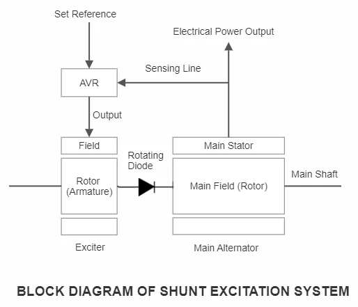
Shunt Excitation System
As shown in the diagram, the AVR senses the output voltage from the stator winding terminals feeding the load in this basic system. It compares this value with the manually set output reference value and regulates the excitation system to increase or decrease the field current based on the output voltage.
The AVR reduces the voltage to the exciter stator, acting as the field, resulting in lower induced emf in the exciter rotor (armature) and hence the rotor current. This exciter rotor current is fed to the main rotor to create the magnetic flux.
As the system uses the stator output voltage to work, its performance deteriorates on high overloads. Also, it has a low short-circuit capability.
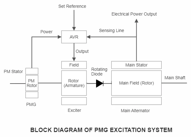
Permanent Magnet Generator (PMG) Excitation System
You can use the PMG excitation system to allow the AVR to function independently of the stator output voltage. This method only reads the sensing voltage from the output terminals of the stator but uses a separate PMG mounted on the same shaft to provide a constant voltage supply for the proper functioning of the AVR, independent of the main stator voltage.
The balance functioning is the same as the shunt excitation system. PMG system has a high overload capacity (typically 300% for 10 seconds) and can start the generator with these loads.
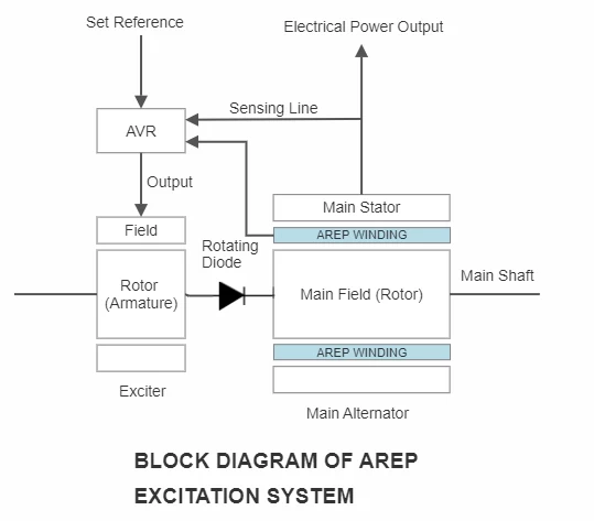
AREP Excitation System
This system functions with the help of two separate auxiliary windings that are installed on the stator. The voltage of the first winding depends on the stator output voltage, and the voltage on the second depends on the current drawn by the load.
Power to the AVR comes from the auxiliary winding independent of the sensing line and any harmonics due to non-linear loads. This system lends a high short-circuit capability to the alternator.
Starter
The starting system has already been covered in the above sections.
Fuel Tank
Earlier portable generators had steel or aluminum fuel tanks. But modern-day tanks are made from plastic and sit on the molded plastic shroud over the engine. As mentioned earlier, the fuel line connects the fuel tank to the carburetor.
Outlets
The output terminals of the armature are extended internally and are connected to the power outlets. Most modern generators provide 120V / 240 V outlet combinations depending on the ratings of the generator. The higher the rating, the more outlet combinations you get.
You can use these outlets to hook up your generator and provide electricity to your house. The various ways to connect the generator power to loads are:
- Through plugs and extension cords.
- Using an interlock kit.
- Manual Transfer switches for the entire house.
- An automatic transfer switch (ATS).
Safety & Controls
Engine Management Controls carry out many important functions like
- Enriching the air-fuel mixture for cold starts.
- Adjust the rpm as the load varies,
- Shutting down the engine in case of inadequate oil pressure, excessive temperatures, excessive buildup of carbon monoxide, etc.
- Idle control.
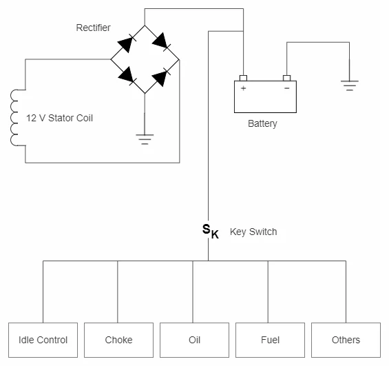
The control system usually consists of a battery, a 12V stator winding, and a full-wave rectifier. The ground return for the system is through the engine block and the metal frame of the generator.
Many generators, particularly smaller ones, provide power to the controls and the battery through the flywheel alternator. Permanent magnets are placed on the flywheel rim to induce voltage into one or more pairs of stator windings, usually at 12 V. If the under-flywheel alternator has only one winding, the output will be intermittent.
A half or full-wave bridge rectifier provides the required 13.5V Dc at 3600 RPM. The rectifier is many times integrated with a voltage regulator.
Fuel Cut-Off Valves
Each generator carries two cut-off valves,
- The inline shutoff valve and
- The solenoid-operated valve at the carburetor.
The inline cutoff valves are manually operated; in their absence, the fuel in the carburetor bowl will evaporate. This will form part of evaporative emissions from the portable generator, and the generator may fail to comply with the CARB or EPA regulations. Diesel engines may even use this valve to shut off the engine.
The solenoid-operated valve is a normally closed valve that prevents any fuel from reaching the main jet after the shutdown. The inlet and exhaust track temperatures are high enough to cause backfiring even without the spark.
Oil Pressure Sensor
It is located near the oil filter or the oil pump. It is always connected to the low-voltage side of the ignition. The engine must be shut down once the low oil pressure condition arises. These sensors are pressure-actuated switches that are normally open and close on sensing low pressure. While it is manufacturer specific, and you should check the owner’s manual for the exact value, the sensor is usually set at 1 Kg / cm2.
Oil Level Sensor
They, like oil pressure sensors, are designed to shut down the engine if there is a lack of enough oil in the system. Sometimes they malfunction to shut down immediately after the engine runs, particularly after the oil change with a different brand due to foam formation.
Idle control
Many engines are designed to run at reduced speeds under partial loads. The speed reduction is in the range of 30 to 40% and leads to a reasonable fuel consumption reduction. This reduction is achieved through the “Idle Control Function” managed by an Electronic Control Unit (ECU).
ECU commands a carburetor-mounted solenoid valve or a stepper motor to close the throttle valve under light load conditions partially. The load sensing happens at the generator output leads or a dedicated stator winding.
Conclusion
We hope our in-depth article on “How Do Portable Generators Work” has given you a lot of insight into the functioning of their systems and subsystems that will be of practical use to you. If you require any further guidance, feel free to comment or write to us, and we will respond back in a reasonable time.