A lot of people are still confused about the difference between inverter generators and conventional generators.
Conventional generators have been the go-to choice for a long, but they’re starting to become outdated. An inverter generator produces pure sine wave AC current, which is more efficient and can run sensitive electronics against the dirty power of conventional machines.
An inverter generator is a perfect solution for anyone who wants the security of a backup generator with the efficiency of an inverter. Inverter generators are smaller, lighter, and quieter than conventional generators, making them ideal portable generators.
This article will explain to you what is an inverter generator, the basics of inverters, the types of inverter generators, how an inverter generator works, and all the main differences from the traditional generator.
What is the Purpose of a Generator with an Inverter?
Conventional generators have only two speeds – with their throttles wide open or fully off. Hence, they run only at 3600 RPM. These generators shed their RPMs under load though this correlation between generator load and RPM is crude.
You will find that the voltage and frequency of an inverter generator are uncoupled from the RPM. So, their engine speed is much lower than at full throttle. This leads to better fuel efficiency, lower fuel consumption, emissions of pollutants, and noise levels.
In addition, they produce clean power output with lower total harmonic distortion making them an instrument of choice. With them, the electronic devices do not overheat, the fidelity of sound systems is ensured, and the battery charging happens quickly.
Inverter generators produce cleaner power by adding a component, “Inverter,” that processes the raw, dirty AC power from the alternator and conditions it with the help of a microprocessor-controlled multi-step process.
They weigh 25 to 30% less than any conventional portable generator of a similar rating, allowing easy portability and making them perfect for camping, tailgating, or power outages.
Inverter generators have the inherent paralleling capability, allowing two generators to operate in parallel when a high power output is needed.
Please read through the article to understand how an Inverter generator works to achieve the above results. You will also learn the major differences between conventional and inverter generators.
What is an Inverter Generator & How Does It Work?
It is better to familiarize yourself with the construction of an inverter generator before taking a plunge to understand its functioning.
Key Constructional Features
The key constructional elements of an inverter generator are an inverter cell, multipole stator, permanent magnet rotor, stepper motor, and a large-sized fan that is essential for the cooling and proper functioning of the inverter. The rotor that cantilevers off the engine crankshaft without an outboard bearing can serve the function of a flywheel.
The stator of any conventional generator encases the rotor. Inverter generators have an exactly opposite arrangement where the rotor surrounds the stator. The rotors of inverter generators carry permanent magnets instead of excitation circuits. An inverter generator automatically adjusts its speed to match the load by using its stepper motor.
Instead of simple two-pole cores in most conventional portable generators, the alternators of inverter generators have permanent magnet rotors and much smaller multipole stators. They produce raw, high-frequency (greater than 20,000 Hz), multiphase AC electricity. The voltage of this electrical power is usually upwards of 200V.
The power in any inverter generator goes through three transformations. First, the mechanical energy produced from burning the fuel source is converted to a high-frequency alternating current, which is then rectified to obtain a 180V – 200V direct current. This DC current is then chopped into segments and fed to inverters that convert DC power to low voltage single phase AC electrical current.
Types of Inverter Generators
Unfortunately, the inverter generator technology is costly and limited to about a 7 kW rating at present. It is not easy to get the inverter cell repaired. You are left with replacement as the only alternative if the inverter cell goes faulty. And replacements are expensive.
Due to their cost, three major types of inverters are used in portable generators. There is always a trade-off between the waveform purity and the cost. The three types of inverters are
- Square wave inverters
- Modified square wave inverters
- True sine wave inverters.
Before dealing with them in detail, you should familiarise yourself with how a basic inversion process works.
Principle of Inversion
Inverters work by creating a sine wave approximation through the production of one or more stepped square waves. The amplitude of these square waves is chosen to approximate a sine wave. Each voltage step requires its switch, voltage supply, and control circuitry. The more steps an inverter has, the more its output will approximate a sine wave. But, more steps will also make it expensive.
Most square and modified square wave inverters use MOSFETs as switches. Any MOSFET can work only in two states, “On” and “Off.” These switches do not modulate, but the AC current passing through them undulates. The effectiveness of an inverter depends on the degree to which its switches can mimic the sine wave. The microprocessor controllers manage the On-Off times of these MOSFET switches to produce such waves.
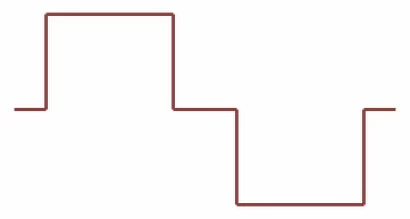
The figure shows the single-step (red) and three-step (green) approximation of the sine wave. The single-step approximation shown in red is known as the square wave. The green-colored approximation has three steps termed the modified square wave. Needless to mention that the three-step version is a closer approximation of a pure sine waveform.
Kindly look at the diagram below to understand how such approximations work. The diagram shows a typical three-step inverter. The alternator’s output AC voltage is converted to 3 DC voltages V1, V2, and V3 in increasing order of magnitude.
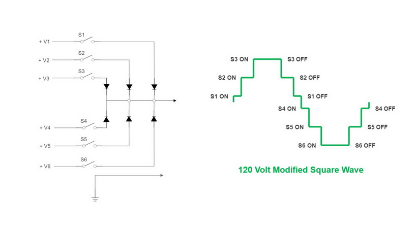
A microprocessor controls these steps to generate a modified square wave, also known as the pseudo-sine waveform. It first sequentially switches S1, S2, and S3 “ON.” When S2 is switched on, S1 is already on. Therefore, the two DC voltages add up to produce the sum of the voltages V1 and V2. When all three switches are in the “ON” state, we reach the positive peak of the voltage wave.
This is followed by sequentially switching.
- S3, S2, and S1 off to bring the waveform from the positive peak to zero.
- S4, S5, and S6 on to produce the negative peak of the waveform.
- S6, S5, and S4 off to complete one full wavelength of the waveform.
This process is repeated 60 times a second to feed power to the connected electrical devices. As already stated, more steps will more closely mimic the sine waveform at an increased cost.
Applications of different types of inverters
Square wave generator
A square wave generator can run simple tools with universal motors without any issues, not other loads. Hence their use is found only in construction sites with lower weight and cost and smaller size, and fuel efficiency provide more benefits than any other conventional portable generators.
Modified square wave (MSW) generators
These types of inverter generators are also known as “Modified sine wave,” “Pseudo-sine wave,” and “Cyclo converters.” They are low in cost and slightly more fuel-efficient than other conventional generators. They have the ability to operate most household electrical appliances satisfactorily. This allows them to feature in most reputed manufacturers’ residential, Standby, Economy, Industrial, and RV ranges.
The modified square wave is obtained by converting alternator AC power to DC and then inverting it back to AC in what is known as a Double Conversion Process. It provides cleaner, stable and reliable power compared to any conventional portable generator with AVR.
However, MSW has certain drawbacks.
- It can overheat sensitive electronic equipment like hard drives, mobile phones, video cameras, and computers.
- The peak voltage of the modified square wave is lower than the true sinusoidal wave. It is typically in the range of 142 to 145 V as against 169 V of a true sinusoid. Hence, most appliances that depend on peak voltage, like a car battery, do not operate as effectively.
True Sine Wave Generators
Also known as Pulse Width Modulation (PWM) inverters, they provide a near sinusoidal current using microprocessor-based control modules.
The recent rapid developments in the field of power electronics, including IGBTs (Insulated Gate Bipolar Transistors), and microprocessor-based control systems, have made inverter modules working on pulse width modulation principles affordable.
However, these are still used only in applications requiring very quiet operation or in the Deluxe series featuring the best inverter generators of the manufacturers. For example, the EU series of Honda uses pulse width modulation.
PWM inverters provide higher performance levels with a waveform distortion factor of less than 5% and are considerably more efficient than any traditional generator.
A PWM inverter consists of a converter section, a DC link, a pulse width controller, a throttle controller, voltage and current sensors, and an inverter section constituting the IGBT switches. The block diagram of a PWM inverter is shown below.
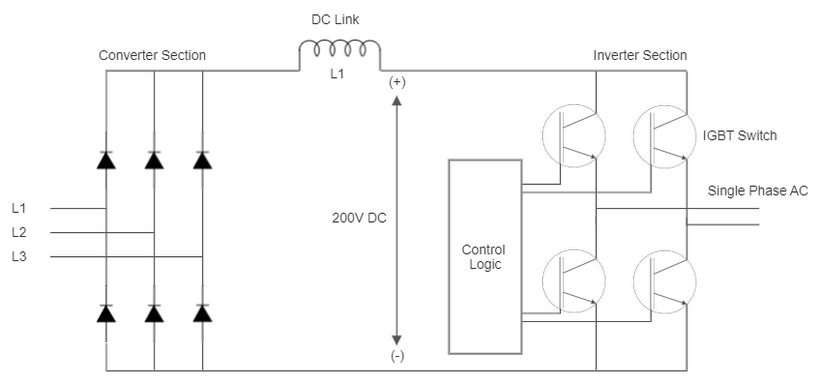
The converter section carries a fixed diode bridge rectifier to convert the multiphase high-frequency AC current to the DC voltage of about 200 V. This DC voltage is fed to the inverter module carrying high-speed IGBT switches operating at a frequency of several kHz. IGBTs can switch “ON” in less than 400 ns and switch “OFF” in approximately 500 ns.
The voltage and frequency of the generated power output are governed by the PWM controller logic. The control logic staggers the IGBT on-off times with reference to a 60 Hz, 120 V AC signal.
During the generation of the positive half cycle by the inverter, the IGBT connected to the positive terminal of the DC link is switched on and off by the controller. This switching happens for variable intervals and at variable rates. The logic works as follows:
- During the beginning of the positive half-cycle, the IGBT switches are turned “ON” for shorter periods of time. This allows only a small amount of the current to build up, as the sinusoidal waveform requires.
- The duration of the IGBT “ON” period is then progressively increased.
- If the IGBT is left “ON” for longer, the current buildup is higher.
- The “ON” period increases until the positive peak is reached.
- The On-time of the IGBTs is progressively decreased in a similar manner, thereby decreasing the current to construct the decreasing portion of the positive half cycle.
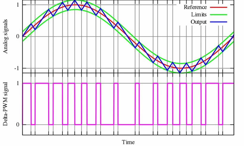
- Delta_PWM.png: Cyril BUTTAY
- derivative work: Krishnavedala (talk)
- CC BY-SA
To construct the negative half of the AC sinusoidal waveform, the IGBT connected to the negative terminals of the DC link is used with the control logic similar to the positive half. The fixed DC link voltage is clipped or modulated to generate variable voltage or frequency.
You would have understood by now that power inverter generators work by processing raw electrical energy produced by the alternator, and its voltage and frequency are not related to the engine speeds. The PWM logic ensures voltage stability within 1% of the rated voltage and frequency stability within 0.01 Hz. This results in cleaner power with harmonic distortion of less than 5%.
The throttle control logic provides the signal to the stepper motor to match the engine speed with the load.
You will now have a good grasp of inverter generators and how they work. Also, you would have started recognizing its differences from the traditional generator. Let us highlight some of them for you.
Inverter Generator Vs Generator?
Let us now take a deep look into this and list down these key differences between generator vs Inverter.
Construction: The rotor in any regular portable generator is encased within the stator. The arrangement is opposite in the inverter generator as the rotor surrounds the stator.
The rotor in the conventional generator is supported by a bearing on the outboard end that keeps the rotor centered within the stator. The inboard end of the rotor is supported by engine main bearings.
The rotor is connected to the crankshaft in a cantilever arrangement without any outboard bearing in an inverter generator.
Electrical winding arrangement in rotor and stator: A conventional portable generator has a two-pole rotor fed from the AVR through a slip ring and brush arrangement.
Most inverter generators use rare earth permanent magnets as the field to generate electricity in the stator. The stator has a multi-pole and multiphase winding to produce the high-frequency multiphase power output.
Speed of the generator: By design, two-pole conventional generators run at a constant speed of 3600 rpm. They do shed some speed with the introduction of load, but onboard frequency governors try to match the design speed.
On the other end, any inverter generator runs at speed matching the load. This is achieved by an onboard stepper motor controlled by the throttle logic.
Voltage and frequency regulation: Conventional portable generators experience a change in voltage and frequency when the load is imposed or removed from the generator. These changes can substantially impact the performance of the connected appliances. Hence, these generators are equipped with automatic voltage regulators (AVRs) and frequency governors to counter the changes in voltage and frequency.
The voltage and frequency in inverter generators are decoupled from the engine speed and only controlled by the inverter control logic to keep them within 1% and 0.01 Hz, respectively.
Noise Level: Since they change their engine speed to match the load, most inverter generators produce a noise level of less than 60 dBA that matches the levels of a quiet conversation. Conventional portable generators, on the other hand, generate noise levels above 70 dBA.
Fuel Efficiency & Emissions: Reduced speed operation makes the inverter generators more fuel-efficient than any conventional generator of a similar rating. This lower consumption of fossil fuels also results in fewer emissions.
Paralleling Capabilities: It is possible to operate two or more inverter generators with lower power output ratings if more power is required. Many models of conventional generators do not possess paralleling capabilities.
Portability: inverter generators are much smaller and lighter than any conventional portable generator of the same rating, making them more portable.
Ratings & Cost of the generator: Most inverter generators carry a much higher price tag for any given power requirement. Their maximum rating is in the range of 6 to 7 kW, and they are not suitable to power very heavy loads.
What is Better – A Generator or an Inverter Generator?
By now, you will have a concise idea of the advantages and disadvantages of both types of generators in the discussion. The selection of either of the two is a techno-commercial decision considering your technical power requirements against the capital and the running cost of the generator.
Conclusion
Inverter generators are becoming more popular because they have a lot of advantages over traditional generators. An inverter generator is a great option if you are looking for a portable power source. They are quieter, lighter, and more fuel-efficient than traditional generators. Inverter generators also produce less noise and vibration, so they are ideal for camping or tailgating. If you want to know more about the different types of inverter generators available, please leave a comment below. We would be happy to answer your questions.