You might have frequently heard the term Harmonics, particularly if you use a lot of sensitive electronics equipment. But you not sure what they are, or what the terms like desirable, undesirable components, Total harmonic Distortion, Distortion Factor Demand Distortion, Form Factor, Voltage Ripple Factor, etc means, then read through this article on “Mathematical Treatment of Harmonics in Electrical Systems” to have a clear and concise understanding of Harmonics and all the related concepts.
Harmonic Quantities
Let us introduce you to several basic terms related to the harmonics phenomena. If you already know these, feel free to skip to the next sections.
What Is Harmonics?
Electrical Energy is distributed on industrial AC power supply networks in a three-phase sinusoidal system. One of the desired characteristics of the system is the waveforms should always remain as close to a pure sine wave as possible.
In practice, the voltage and current waveforms differ considerably from the desired ones. The actual waveform carries many sine waves of different frequencies superimposed over the desired power frequency waveform. Such power with harmonics is also termed Dirty Power.
The power frequency waveform is also commonly referred to as the “fundamental frequency” or “fundamental component” or even simply as the “fundamental“.
Harmonic Component
The other sinusoidal components of different frequencies, referred to above, distort the original waveform and are referred to as “harmonic components” or simply the harmonics of the fundamental.
One of the interesting characteristics of the harmonics is that they are a multiple of the fundamental frequency. The amplitude of any harmonic is usually denoted as a percentage of the amplitude of the fundamental.
Harmonic Order
Also known as the harmonic number, it designates any harmonic by the ratio of its frequency fn and the fundamental f1.
Hence, the Harmonic Order n has a frequency  .
.
The harmonic order of the fundamental frequency  is 1. The harmonic order “n” is also known as the nth harmonic.
This means that for a 60 Hz system, the 3rd harmonic happens at 180 Hz, the 5th at 300 Hz, the 7th at 420 Hz, and so on.
Frequency Spectrum
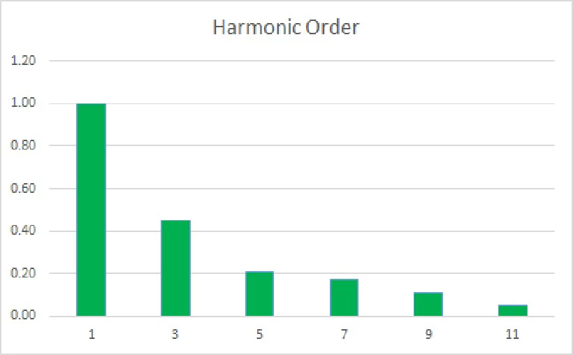
A frequency spectrum is a histogram that plots the amplitude of any network’s harmonic components as a function of harmonic order. A sample spectrum is shown below. The amplitudes generally decrease with an increase in harmonic number.
Harmonic Distortion
The diagram below shows the fundamental waveform getting superimposed by a third harmonic. You can also see the resultant waveform as it appears on an oscilloscope. See the ripple effect caused by the superimposition. These ripples are the harmonic distortion of the fundamental.
Waveform
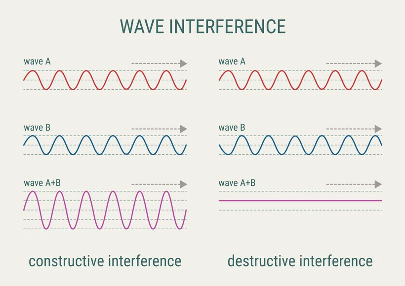
As you may already know from high school physics, the superimposition of two or more waves results in constructive or destructive interference. Constructive interference raises the amplitude, while destructive interference lowers it.
Most portable generators have two pole salient pole rotors. Due to this arrangement, all the even harmonic components cancel out, leaving only the odd ones in the circuit. The modern test equipment can carry accurate THD measurements considering harmonic frequencies up to 63rd.
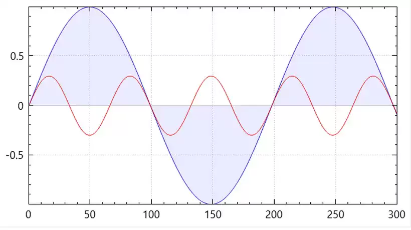
The diagram below shows the fundamental and the third harmonic components in a power system. The blue is the fundamental waveform, and the red is the third harmonic. Note that its frequency is three times that of the fundamental voltage.
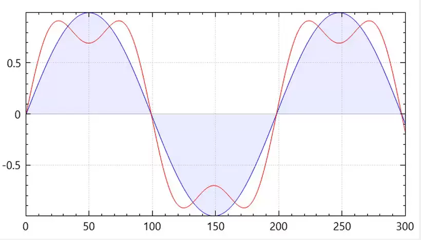
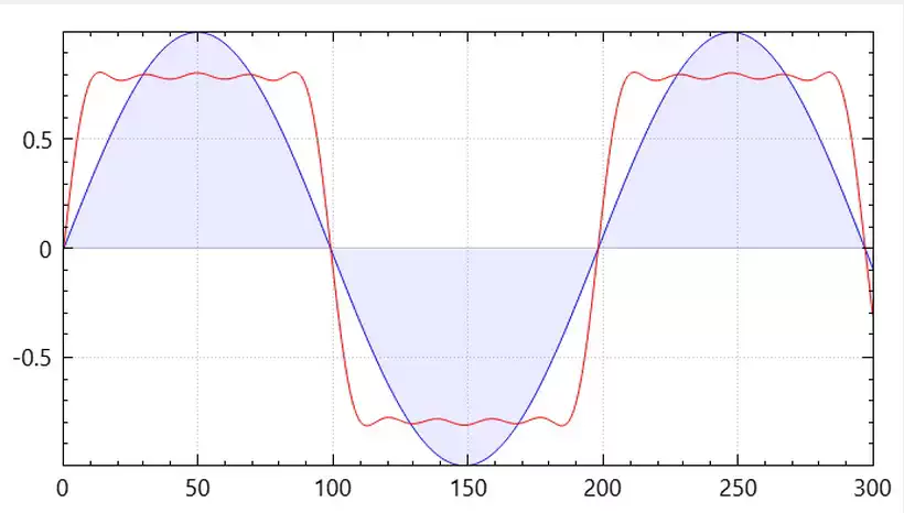
The red waveform in the below image shows the combined effect of the above two components on the produced voltage waveform. The blue wave is the desired or the fundamental waveform, while the red is the actual waveform with the 3rd harmonic.
As more harmonic components are added, the combined waveform will shift toward the square waveform shape. This is evident from the below-distorted waveform with odd harmonic components up to the ninth harmonic.
Individual Harmonic Ratio
This measure is used to quantify the disturbances caused in the power supply network by the individual component. The harmonic ratio for any order n is the ratio of the RMS value of the nth component to that of the fundamental.
Hence it is equal to  , where
  is the RMS voltage of the nth component and
  for the fundamental.
The Mathematical Expression Of The Distorted Wave
While considering the distortion in any power application, you need to be clear about the desired waveform and the undesirable waveform. The definition of the two and the related mathematical quantities vary in the converter and inverter applications as you desire a DC and sinusoidal AC output in these two types of devices, respectively. Let us first look at the concept of RMS values and Fourier analysis as they play an important role in Harmonic analysis.
RMS Values Of Quantities In Wave Under Distortion
It is usual to express the voltage and current harmonics in terms of their RMS values because the heating effect produced in the related circuit depends on them. RMS values for all sinusoidal quantities are given by their maximum instantaneous values divided by  .
.
When any distorted quantity is in a steady-state condition, the total energy dissipated by it is the sum of the dissipated energies by the individual harmonic components, i.e.
![\[I^2Rt = I_1^2RT + I_2^2RT + I_3^2RT + \ldots + I_n^2RT\]](https://yourpowerguide.com/wp-content/ql-cache/quicklatex.com-9ab8ce9d5f452fa9fbd331324b8ef20f_l3.png "Rendered by QuickLaTeX.com")
or,
![\[I^2 = I_1^2 + I_2^2 + I_3^2 + \ldots + I_n^2\]](https://yourpowerguide.com/wp-content/ql-cache/quicklatex.com-1e916f4fc9d019eb34c8c72434bd42a7_l3.png "Rendered by QuickLaTeX.com")
if the resistance is constant.
From the above expression, the RMS current is the square root of the sum of squares of currents of different orders.
The measurement of RMS values for any distortion can be done by spectrum analysis or by using instruments designed to measure the true RMS quantities directly.
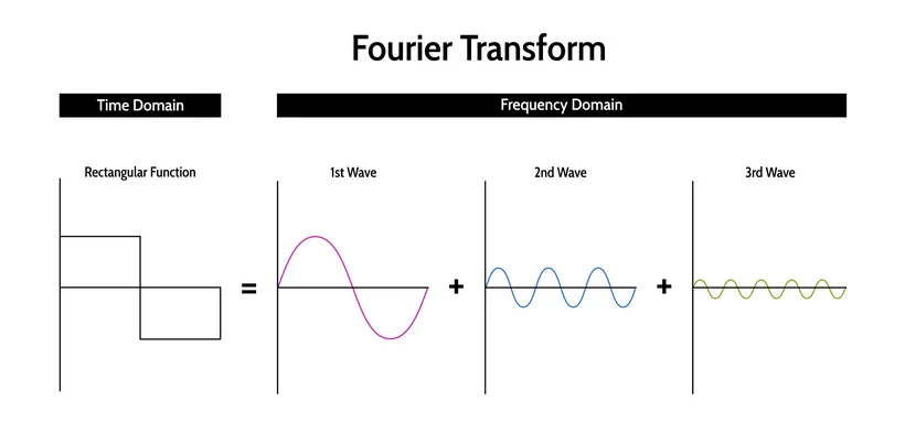
Fourier Analysis
Fourier series is used to represent any periodic phenomena mathematically. The expression of the series is
![\[y(t) = Y_0 + \sum\limits_{n=1}^\infty Y_N \sqrt{2} \sin (nwt-\phi_n)\]](https://yourpowerguide.com/wp-content/ql-cache/quicklatex.com-971d1900e4dfae7a2a42c71ac38c026b_l3.png "Rendered by QuickLaTeX.com")
where  represents the amplitude of the DC component. is zero at a steady state in electrical power distribution. In fact, IEEE 519 does not allow harmonics of order 0 to exist in power systems.
 is the RMS value of the nth harmonic, and
  is the phase angle of the nth harmonic at t = 0.
You can neglect the orders above 50 as per the relevant standards.
Analysis of an AC to DC converter
Let us first start with the analysis of a converter where a constant DC output is desired.
![\[v_0(t) = V_0 + V_1 \sin wt + V_2 \sin 2wt + V_3 \sin 3wt + \ldots\]](https://yourpowerguide.com/wp-content/ql-cache/quicklatex.com-e725dc09389adb1c5b4bbc6d756735e3_l3.png "Rendered by QuickLaTeX.com")
Any content other than the pure DC component  in the above equation forms the ripple content, which is undesirable. Here
  is the first harmonic,
  is the second harmonic,
  is the third harmonic, and so on. The RMS value of the ripple
![\[= \sqrt{\frac{V_1^2}{2} + \frac{V_2^2}{2} + \frac{V_3^2}{2} + \ldots}\]](https://yourpowerguide.com/wp-content/ql-cache/quicklatex.com-dd4305b4bd5da0c0b327dc81f3db7090_l3.png "Rendered by QuickLaTeX.com")
and the peak-to-peak ripple = 
Harmonic Analysis
Let us consider the output of the full wave rectifier, which produces a positive half-cycle corresponding to each of the positive and negative half-cycle of the input sinusoidal waveform. Hence the frequency of the output voltage is twice that of the input voltage. Hence only even multiples of the input frequency will be there. The equation of the output voltage will be
![\[v_0(t) = V_0 + V_2 \sin 2wt + V_4 \sin 4wt + V_6 \sin 6wt + \ldots\]](https://yourpowerguide.com/wp-content/ql-cache/quicklatex.com-c778eadc6d07577c253eb685ef448ce9_l3.png "Rendered by QuickLaTeX.com")
The average of the output voltage
![\[v_0(avg) = V_0\]](https://yourpowerguide.com/wp-content/ql-cache/quicklatex.com-8a3800f8143f3555ab50aed568a038b2_l3.png "Rendered by QuickLaTeX.com")
The RMS value of the output voltage
![\[v_0(rms) = \sqrt{V_0^2 + \frac{V_2^2}{2} + \frac{V_4^2}{2} + \ldots}\]](https://yourpowerguide.com/wp-content/ql-cache/quicklatex.com-8ce62e355dad28929886ffeb232fef18_l3.png "Rendered by QuickLaTeX.com")
Next, let us look at the RMS value of the harmonic components. These are calculated in the same way as the RMS value of the output voltage, except that the desired components are not considered in the calculations.
![\[v_h(rms) = \sqrt{\frac{V_2^2}{2} + \frac{V_4^2}{2} + \ldots}\]](https://yourpowerguide.com/wp-content/ql-cache/quicklatex.com-3dc39baa0ab1d8d001462833d7d66e0a_l3.png "Rendered by QuickLaTeX.com")
The  can also be calculated from the equation for
  above by squaring the two sides, taking the
  term to the left side, and then taking the square root of it. Hence
![\[v_h(rms) = \sqrt{V_0^2(rms) - V_0^2}\]](https://yourpowerguide.com/wp-content/ql-cache/quicklatex.com-28c536dddcf2b39a67ec7d41d6546e85_l3.png "Rendered by QuickLaTeX.com")
The voltage ripple factor (VRF) is defined as the ratio of the undesirable terms and the desirable terms, which are and , respectively. The VRF indicates the harmonic content in  as a fraction of the DC output, .
![\[VRF = \frac{v_h(rms)}{V_0} =\frac{\sqrt{v_0^2(rms) - V_0^2}}{V_0}\]](https://yourpowerguide.com/wp-content/ql-cache/quicklatex.com-e6107f41855caf7290e9797715a2a627_l3.png "Rendered by QuickLaTeX.com")
![\[= \sqrt{\left(\frac{v_0(rms)}{V_0}\right)^2 - 1}\]](https://yourpowerguide.com/wp-content/ql-cache/quicklatex.com-3fe7955379b36f7a5c0c23fb175dc266_l3.png "Rendered by QuickLaTeX.com")
The ratio in the first term inside the square root above is known as the Form Factor, FF, i.e.,
![\[FF = \frac{V_0(rms)}{V_0}\]](https://yourpowerguide.com/wp-content/ql-cache/quicklatex.com-a2c445b2bac4606fcec9509fc0fec086_l3.png "Rendered by QuickLaTeX.com")
Hence the equation for the voltage ripple factor in terms of the form factor is.
![\[VRF = \sqrt{FF^2 - 1}\]](https://yourpowerguide.com/wp-content/ql-cache/quicklatex.com-4f42611c461fe8700410ce02a5d530b5_l3.png "Rendered by QuickLaTeX.com")
For obtaining a perfect DC voltage, there should be no undesirable components. In that case, the  will become equal to , the value of form factor = 1 and VRF = Zero. The closer the FF is to 1, the waveform will approach the pure DC. The higher its value, the quality of the DC waveform will be poorer.
Analysis of AC Harmonics
When a sinusoidal input voltage is applied to a circuit, the output current waveform will depend on the load. In turn, the input current waveform gets impacted by the output current waveform or depends on it. The output voltage waveform depends on the input voltage waveform.
If the load current is constant or a DC value, then the source current will be a square or a quasi-square wave and will contain a lot of harmonics. So, the output of a rectifier will always contain voltage harmonics, while the input side contains current harmonics. The equation for the source current is
![\[i_s(t) = I_1 \sin wt + I_3 \sin 3wt + I_5 \sin 5wt + \ldots\]](https://yourpowerguide.com/wp-content/ql-cache/quicklatex.com-7cf2de630970ba5cceb7af3ad00ec0c7_l3.png "Rendered by QuickLaTeX.com")
Since the AC waveform has odd symmetry, the even harmonics cancel out, and only odd harmonics remain. As you may know, for an odd function  .
.
In the AC waveform, the first harmonic or fundamental component is the desirable component, while the other components are undesirable ones. Hence, the rms value of the desirable component is
![\[I_{s1} (rms) = \frac{I_1}{\sqrt{2}}\]](https://yourpowerguide.com/wp-content/ql-cache/quicklatex.com-05f58a08ec01e7114bc3e4327f24f0cc_l3.png "Rendered by QuickLaTeX.com")
The RMS value of the total source current is
![\[I_s(rms) = \sqrt{\frac{I_1^2}{2} + \frac{I_3^2}{2} + \frac{I_5^2}{2} + \ldots}\]](https://yourpowerguide.com/wp-content/ql-cache/quicklatex.com-cc61cd3e280818b4b7533ce6564dc5fe_l3.png "Rendered by QuickLaTeX.com")
Similarly, the RMS value of the undesirable component is
![\[I_h(rms) = \sqrt{\frac{I_3^2}{2} + \frac{I_5^2}{2} + \frac{I_7^2}{2} + \ldots}\]](https://yourpowerguide.com/wp-content/ql-cache/quicklatex.com-510869c504cf7a3eca92f247f786f68f_l3.png "Rendered by QuickLaTeX.com")
![\[\implies{I_h(rms) = \sqrt{I_s^2(rms) - I_1^2} }\]](https://yourpowerguide.com/wp-content/ql-cache/quicklatex.com-45ea05e7ded62dd534acb875fbc39659_l3.png "Rendered by QuickLaTeX.com")
![\[= \sqrt{I_s^2(rms) - I_{s1}^2(rms)\]](https://yourpowerguide.com/wp-content/ql-cache/quicklatex.com-5033ed2efb45b54ba3f7135a285870fd_l3.png "Rendered by QuickLaTeX.com")
What is the Mathematical Expression for Total Harmonic Distortion (THD)?
You must now be familiar with waveform distortion, harmonics, various quantities associated with this phenomenon, and their mathematical treatment. With this background, you will now be ready to understand and appreciate the core concepts behind total harmonic distortion, THD, and mathematical treatment. THD is also known as the total harmonic factor and quantifies all the harmonics’ total thermal effects.
THD is the ratio of the two RMS values, the undesirable components, to the desirable components. In other words, it is a ratio of all the harmonics present to that of the fundamental frequency.
![\[THD = \frac{I_h(rms)}{I_{s1}(rms)}\]](https://yourpowerguide.com/wp-content/ql-cache/quicklatex.com-d2c559077595fb865bba618c6be21190_l3.png "Rendered by QuickLaTeX.com")
![\[=\frac{\sqrt{I_s^2(rms) - I_{s1}^2(rms)}}{I_{s1}(rms)}\]](https://yourpowerguide.com/wp-content/ql-cache/quicklatex.com-c922a990ab01379e1ca020b28b2923ae_l3.png "Rendered by QuickLaTeX.com")
![\[= \sqrt{\left(\frac{I_S(rms)}{I_{s1}(rms)}\right)^2 - 1}\]](https://yourpowerguide.com/wp-content/ql-cache/quicklatex.com-96f5d8b96da183df68b613c1b6a6268c_l3.png "Rendered by QuickLaTeX.com")
![\[= \sqrt{\left(\frac{1}{g^2}\right)^2 - 1}\]](https://yourpowerguide.com/wp-content/ql-cache/quicklatex.com-ab9f16fde9139f8b705990849ace650a_l3.png "Rendered by QuickLaTeX.com")
Where g = Distortion Factor, given by
![\[g = \frac{I_{s1}(rms)}{I_s(rms)}\]](https://yourpowerguide.com/wp-content/ql-cache/quicklatex.com-be7239951946e7e01dd813718bf14649_l3.png "Rendered by QuickLaTeX.com")
When the harmonics are present,  , which means that the value of g is always less than 1 or the value of THD is greater than zero.
If the output is a purely sinusoidal waveform or no harmonics are present, the value of  . This implies that the value of g is equal to 1 and
  .
.
The waveform becomes sinusoidal as the g approaches 1.
If we replace the root mean square value of the fundamental with the total load current in the denominator in the ratio above, we get the Total Demand Distortion, TDD.